
High voltage direct current systems are becoming increasingly essential in modern power distribution, renewable energy integration, and industrial automation. Among the critical components ensuring safe and efficient operation are switching devices such as the high voltage direct current relay and high voltage direct current contactors. These components handle demanding electrical loads, interrupt fault currents, and provide isolation. However, their correct application requires rigorous attention to installation practices, scheduled maintenance, and systematic troubleshooting.
Before discussing installation or maintenance, one must distinguish between a high voltage direct current relay and high voltage direct current contactors. Although often used interchangeably in casual language, they serve different roles. A high voltage direct current relay is typically designed for control and protection circuits, operating with lower coil power and switching moderate loads. In contrast, high voltage direct current contactors are built for frequent load switching under high current and voltage, featuring arc extinguishing chambers and robust contacts.
Both devices share common challenges: DC arcs do not self-extinguish at zero current as AC arcs do. Consequently, these components incorporate magnetic blowouts, permanent magnets, or gas-filled enclosures. Understanding this physics is key to proper handling.
| Feature | high voltage direct current relay | high voltage direct current contactors |
|---|---|---|
| Primary function | Control/protection switching | Load making/breaking |
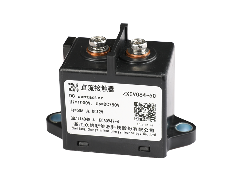
| Typical current rating | Low to medium (up to ~50 A) | Medium to high (100 A to 1000 A+) |
| Arc quenching method | Sealed chamber + magnets | Arc chute + magnetic blowout |
| Coil power consumption | Low | Higher |
| Mechanical life (operations) | 100k–500k | 50k–200k |
Proper installation directly impacts reliability and safety. Follow these principles for both high voltage direct current relay and high voltage direct current contactors.
Most high voltage direct current relays are position-sensitive due to magnetic blowout design. Consult the datasheet. Common rules:
Installation must include adequate clearance around the device. The arc expelled during fault interruption (although minimal in sealed units) requires:
Pay special attention to the polarity of main terminals on high voltage direct current contactors. Most are marked (+) and (-). Incorrect connection drastically reduces arc extinction capability. For bidirectional models, verify the datasheet.
Unlike low-voltage AC contactors, high voltage direct current relays cannot be serviced by simply cleaning contacts, as many are hermetically sealed. However, systematic inspection extends life.
Measure millivolt drop across closed main contacts with a micro-ohmmeter (1 A to 10 A test current). Compare to initial value. Drastic increases (>20%) suggest contact erosion.
| Condition | Millivolt drop (typical for 200 A device) | Action |
|---|---|---|
| New | 5–15 mV | Baseline |
| Acceptable | 15–25 mV | Continue monitoring |
| Marginal | 25–40 mV | Plan replacement within 3 months |
| Critical | >40 mV | Replace immediately |
Cycle the device 5–10 times without main power. Listen for crisp, single-click closure. Multiple clicks indicate contact bounce or mechanical wear.
Dust, humidity, and corrosive gases degrade performance. For high voltage direct current contactors in outdoor enclosures:
Troubleshooting high voltage direct current relay systems requires logical isolation: control side vs. main circuit, mechanical vs. electrical. Below is a structured approach.
Possible causes:
Check: Control wiring, PLC output health, series auxiliary contacts.
Dangerous condition. Immediate actions:
Seen only in non-hermetic or vented high voltage direct current contactors. Contributing factors:
Symptoms: relay picks up then drops out randomly. Likely causes:
Diagnostic: Monitor coil voltage with a fast data logger. Drop below dropout voltage (typically 10–20% of rated) causes release.
| Symptom | Most Likely Cause | Check Method | Corrective Action |
|---|---|---|---|
| Coil hot but no pull-in | Armature stuck | Manual actuation (power off) | Replace, clean debris |
| Slow opening | Contact welding | Measure contact voltage drop with coil off | Replace contactor |
| Sparking at terminals | Loose connection | Torque wrench | Retorque, clean contact faces |
| Intermittent closure | Low coil voltage | Measure at coil during operation | Upgrade power supply or reduce wire length |
| Uneven contact wear | Wrong polarity | Compare terminal markings | Reverse main terminals (if bidirectional) |
No amount of maintenance can restore a worn-out high voltage direct current relay or high voltage direct current contactors. Replace immediately if:
Always follow lockout/tagout procedures before touching main terminals. High voltage DC systems store energy in capacitive and inductive loads. Discharge capacitors and short cables to ground. Use rated PPE: gloves with leather protectors, arc-rated face shield, and voltage-rated tools.
In summary, mastering the high voltage direct current relay and high voltage direct current contactors is not about memorizing numbers but understanding physical principles: arc extinction, magnetic blowout polarity, contact resistance trends, and environmental resilience. A systematic approach to installation, periodic maintenance using measured data, and logical fault isolation will ensure decades of reliable service.


Copyright © 2015-2021, Zhejiang Zhongxin New Energy Technology Co., Ltd. All rights reserved Technical Support:Smart cloud Electromagnetic Relay Manufacturers China Relays Factory


 English
