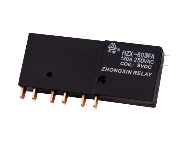
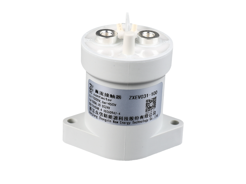
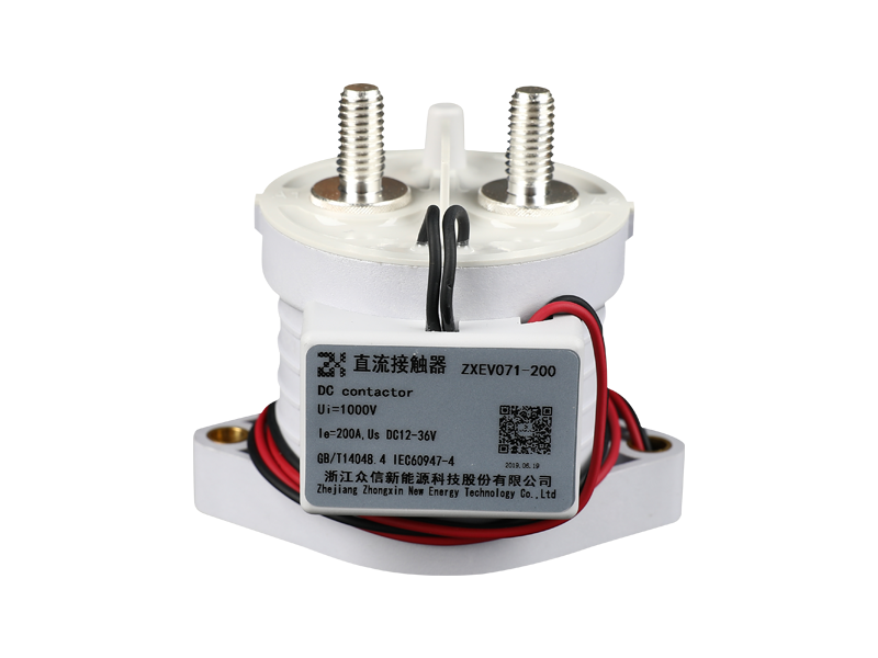
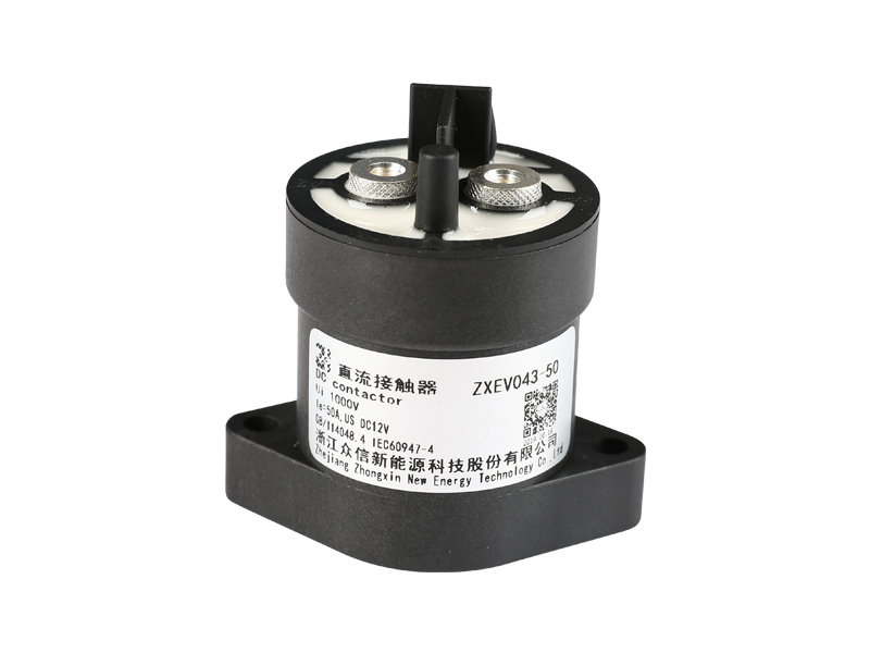
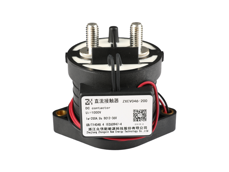
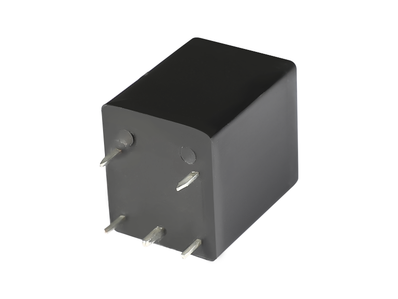
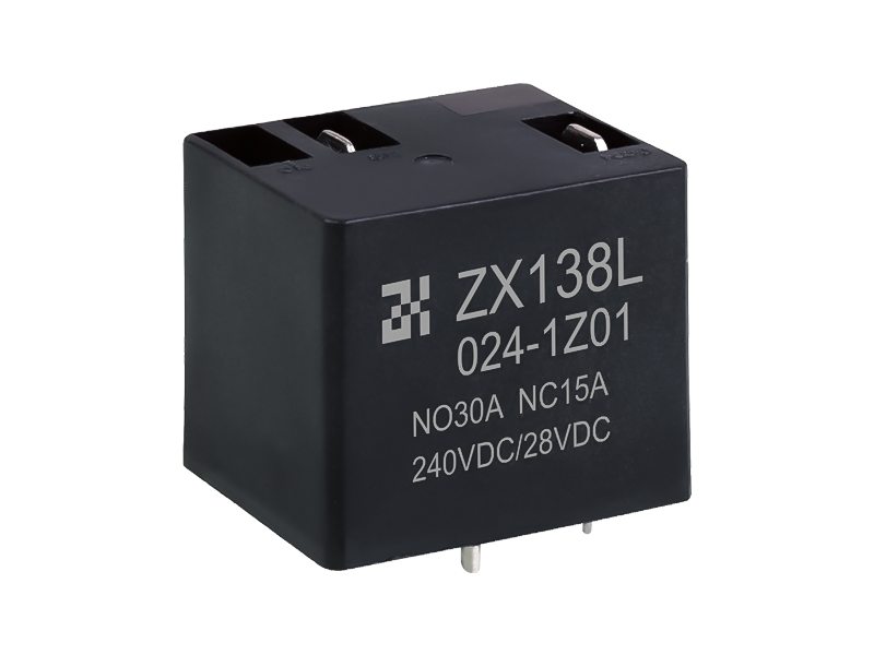
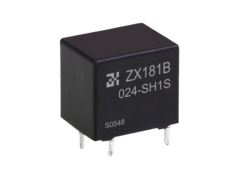
The definition of relay: a relay is an automatic control system component that will produce a jumping change in cardiac output when the output (electricity, magnetism, sound, light, heat) reaches a certain value.
First, the principle and characteristics of the relay (relay)
When the output (such as voltage, current, temperature, etc.) reaches the standard value, the household appliance that makes the controlled output power circuit on or off. It can be divided into two types: electrical equipment quantity (such as current, voltage, frequency, output power, etc.) relays and non-power consumption (such as temperature, working pressure, speed, etc.) relays. It has the advantages of fast action, stable operation, long service life and small size. Widely used in power engineering maintenance, automation technology, fitness, remote control, precise measurement and communication equipment.
Relay is a kind of electronic device control component, it has automatic control system (also known as input control circuit) and automatic control system (also known as output control circuit), generally used in automatic control circuit, it actually uses smaller A "control switch" that manipulates a large current. Therefore, it plays the role of self-regulation, safety protection, and conversion of power circuits in the power circuit.
1. The principle and characteristics of electromagnetic induction relay
Inductive relays are generally composed of transformer cores, coils, flow coils, contact springs, etc. As long as a certain voltage is added to both sides of the coil, a certain current will pass through the coil, thereby forming an electromagnetic effect, and the current coil will get rid of the tensile force of the spring and attract the transformer iron under the action of the magnetic force. The core, and then push the moving contact of the current coil and the static contact (open and close contacts) to pull together. When the power supply of the coil is turned off, the adsorption force of the electromagnetic induction also disappears, and the flow coil will return to the original position under the recoil force of the spring, so that the moving contact and the original static contact (normally closed contact) are attracted. In this way, it is attracted and released, so as to achieve the purpose of on-off and disconnection in the circuit. For the "on and off, normally closed" contacts of the relay, it can be distinguished in this way: the static contact in the off state when the relay coil is not connected to the power supply is called "on and off contact"; The static contact of the environment is called "normally closed contact".
Electromagnetic induction relay
2. The principle and characteristics of thermistor reed relay
Thermistor reed relay is a new type of thermal switch that uses thermistor permanent magnet material to detect and control temperature. It consists of a temperature sensor magnetic ring, a permanent magnetic ring, a dry reed switch, a heat transfer mounting piece, a plastic substrate and some other notes. A thermistor reed relay eliminates the need for a coil excitation regulator, instead a magnetic driver powers the switching action caused by a constant magnetic ring. Whether the permanent magnetic ring can provide magnetism to the reed switch is determined by the temperature control characteristics of the temperature sensor magnetic ring.
3. solid state relay (SSR) principle and characteristics
The solid state relay is a four-terminal component with two wiring terminals as input terminals and the other two wiring terminals as output terminals. The protective components are used in the middle to realize the electrical protection of the output.
Solid state relays can be divided into AC type and DC type according to the type of load switching power supply. According to the power switch form, it can be divided into on and off type and normally closed type. According to the form of protection, it can be divided into composite type, transformer protection type and optical protection type, with the largest number of optical protection types.
solid state relay
2. Key Product Performance Parameters of Relays
1. Rated working voltage
It refers to the voltage required by the coil when the relay is working normally. Depending on the model and specification of the relay, it can be AC voltage or DC voltage.
2. Resistance measurement
It refers to the resistance measurement of the coil in the relay, which can be accurately measured by a multimeter.
3. Pull-in current
It refers to the minimum current that the relay can generate the pull-in action. In normal use, the given current must be slightly larger than the pull-in current, so that the relay can work smoothly. The working voltage applied to the coil should generally not exceed 1.5 times the rated working voltage, otherwise a large current will be generated and the coil will be damaged.
4. Release the current
It means that the relay generates a large current released by the action. When the current in the pull-in state of the relay decreases to a certain level, the relay will return to the release state without power. The current at this time is much lower than the pull-in current.
5. Contact conversion voltage and current
It refers to the voltage and current that the relay is allowed to load. It determines the size of the voltage and current that the relay can control, and it cannot exceed this value when used, otherwise it is easy to damage the contacts of the relay.
three, Relay detection
1. Measuring contact resistors
Use the resistor file of the multimeter to accurately measure the normally closed contact and the moving point resistor, and the resistance value should be 0, (a more accurate method can measure the contact resistance value within 100 milliohms); The resistance value of the closing contact and the moving point is infinite. In this way, it can be distinguished which is a normally closed contact and which is an open and closed contact.
2. Measuring coil resistance
The resistance value of the relay coil can be accurately measured with a multimeter R×10Ω, and then it can be judged whether the coil has a lead condition.
3. Accurate measurement of pull-in voltage and pull-in current
Find an adjustable and adjustable power supply and an ammeter, input a set of voltages to the relay, and connect the ammeter in series in the power supply circuit for testing. Gradually increase the switching power supply voltage, and record the pull-in voltage and pull-in current when the relay pull-in sound is heard. It can be accurate, and you can try several times to find the average.
4. Accurately measure the released voltage and released current
It is also the connection detection as mentioned above. When the relay pulls in, gradually reduce the power supply voltage. When you hear the relay release sound again, record the voltage and current at this time, and you can also try a few more times. And get the average released voltage and released current. Under normal circumstances, the released voltage of the relay is about 10-50% of the pull-in voltage. If the released voltage is very small (less than 1/10 of the pull-in voltage), it cannot be used normally, which will damage the power supply. The reliability of the circuit causes threats, and the work is unreliable.
Fourth, the electrical marking and contact mode of the relay
The relay coil is represented by a long box symbol in the power circuit. If the relay has two coils, draw two side-by-side long frames. In addition, mark the letter symbol "J" of the relay in or beside the long frame. There are two ways to express the contacts of the relay: one is to draw them directly on the side of the long frame, which is more visual. The other is to draw each contact into a separate control circuit according to the needs of the power circuit connection. Generally, the same letters and symbols are marked on the contacts and coils of the same relay, and the contact groups are grouped together. number to represent the difference.
There are three basic types of relay contacts:
1. When the moving type (H type) coil is not connected to the power supply, the two contacts are broken. After the power supply is connected, the two contacts are closed. It is expressed with the pinyin prefix "H" of the ligature.
2. When the dynamic break type (D type) coil is not connected to the power supply, the two contacts are closed, and after the power supply is connected, the two contacts are broken. It is expressed with the pinyin prefix "D" of hyphenation.
3. Transformation type (Z type) It is a contact group type. This type of contact group has three contacts, that is, a moving contact in the middle and a static contact on the left and right. When the coil is not connected to the power supply, the moving contact and one of the static contacts is broken and the other is closed. situation, to achieve the purpose of transformation. Such a set of contacts is called a changeover contact. Use the pinyin prefix "z" of the word "turn" to express.
Five, the use of relays
1. Master the necessary standards first
① The switching power supply voltage of the control circuit, the maximum current that can be provided;
②The voltage and current in the controlled circuit;
③The control circuit needs two sets of contacts of which form. When a relay is used, the switching power supply voltage of the general control circuit can be used as the basis for adoption. The circuit should be able to provide enough working current to the relay, otherwise the relay pull-in is not stable.
2. After checking the relevant materials and clarifying the application standards, you can search for relevant materials to find the model specifications and specification models of the necessary relays. If there is an existing relay on hand, you can check whether it can be used according to the materials. Finally, consider whether the specifications are suitable.
3. Pay attention to the capacity of the equipment. If it is used for general high-power electrical appliances, in addition to considering the capacity of the main box, small and medium-sized relays mainly consider the layout of the circuit board. For small and medium-sized appliances, such as toys and wireless remote controls, pocket-sized relay products should be used.

