
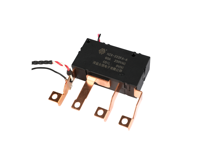
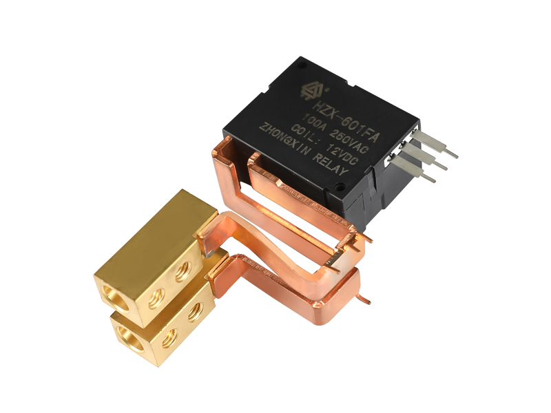
Smart meters have become the backbone of modern utility infrastructure, enabling remote monitoring, load control, and automated disconnection or reconnection of electricity service. At the heart of this switching function lies a critical component known as the magnetic latching relay. Unlike conventional electromechanical relays that require continuous power to maintain a switching state, this type of relay only consumes energy during the moment of switching, making it exceptionally suited for battery-powered or energy-conscious metering applications.
As utility companies push toward smarter grids and remote-controlled infrastructure, the demand for components that combine low power consumption with long-term mechanical reliability has grown substantially. This article explores the technical reasoning behind why this relay type has become the standard choice in smart meter design, covering its working principle, circuit behavior, comparison with other relay types, and practical considerations for engineers selecting components for metering systems.
A latching relay operates on a fundamentally different principle compared to standard relays. Instead of relying on continuous coil energization to hold the contacts in place, it uses a permanent magnet or a mechanical latch to maintain the last switched position even after power is removed. This means the relay stays in its "on" or "off" state indefinitely until a new pulse signal instructs it to change.
The core working sequence can be broken down into distinct stages:
This pulse-and-hold mechanism is what allows a latch relay to draw power only for milliseconds during switching, rather than continuously, which directly translates into significant energy savings across large-scale meter deployments.
To understand why smart meter designers favor this component, it helps to directly compare its behavior against standard relays that rely on continuous holding current.
| Characteristic | Magnetic Latching Relay | Conventional Relay |
|---|---|---|
| Power to maintain state | None required | Continuous holding current needed |
| Energy consumption over time | Very low, pulse-only | Higher, constant draw |
| Behavior during power outage | Retains last switching state | Reverts to default position |
| Heat generation | Minimal, no sustained current | Noticeable during long holds |
| Suitability for battery backup systems | High | Limited |
This table highlights a key operational advantage: in a scenario where grid power is interrupted, a smart meter using a standard relay would lose its switching state and default to a preset condition. A meter equipped with a latching relay retains its exact contact position, which is essential for maintaining accurate billing continuity and avoiding unintended service interruptions.
Two common structural variants are used depending on the complexity of the switching requirement: single coil designs and double-pole double-throw configurations.
A single coil latching relay uses one coil winding to control both the set and reset operations through reversed pulse polarity. This design is compact and cost-efficient, making it a common choice for basic on/off disconnection functions in residential smart meters where only a simple load switch is needed.
A latching relay dpdt configuration offers two independent sets of switching contacts controlled simultaneously. This is particularly useful in metering applications that require switching multiple circuits at once, such as separating the load circuit from a signaling or monitoring circuit, or supporting redundant switching paths for safety-critical installations.
In multi-phase or dual-circuit metering setups, DPDT configurations allow a single control pulse to synchronize the switching of two separate current paths, reducing timing discrepancies between circuits.
Building an effective latching relay circuit for smart meter applications requires attention to several design factors beyond simply selecting the relay itself.
A 12v latching relay is a common voltage class used in metering and control panel applications because it aligns well with standard low-voltage control power supplies already present in many smart meter designs. This voltage level provides a practical balance between coil sensitivity and noise immunity, reducing the risk of unintended switching from electrical interference on the control line.
| Design Element | Typical Practice | Reason |
|---|---|---|
| Pulse width | Short, controlled duration | Ensures full latch without excess energy use |
| Driver circuit | H-bridge or dual transistor stage | Allows bidirectional pulse for set and reset |
| Protection diode | Placed across coil terminals | Suppresses inductive kickback |
| Control voltage | Matched to relay coil rating | Prevents under or over driving the coil |
Utility-grade metering equipment operates under strict long-term reliability expectations, often needing to function without maintenance for over a decade. Several practical factors explain why this relay category has become the preferred switching mechanism in this environment.
Across millions of deployed meters, even a small reduction in standby power draw per device translates into meaningful energy savings at the grid level, since holding-current relays would otherwise consume power continuously for years.
Because the switching position is mechanically and magnetically maintained, a meter retains its connect or disconnect state through power interruptions, avoiding unintended reconnection or disconnection events.
Reduced continuous current flow through the coil lowers internal heat buildup, which in turn slows the degradation of insulation materials and extends the operational lifespan of the switching mechanism.
The pulse-based control method integrates naturally with digital communication protocols used in smart grid systems, allowing utility operators to remotely trigger connect and disconnect commands with minimal signal complexity.
Choosing the right relay for a metering application depends on several technical parameters that should be evaluated together rather than in isolation.
| Parameter | Why It Matters |
|---|---|
| Rated switching current | Must exceed the maximum expected load current with adequate margin |
| Coil voltage class | Should match available control power, such as a 12v latching relay for low-voltage control systems |
| Contact configuration | Single pole for simple switching, dpdt for multi-circuit control |
| Mechanical endurance rating | Indicates expected switching cycles over the product lifetime |
| Operating temperature range | Must accommodate outdoor or enclosure temperature extremes |
Engineers should also consider environmental sealing, since many meters are installed outdoors or in enclosures exposed to humidity and temperature fluctuations. A relay with appropriate sealing and corrosion-resistant contact materials will maintain reliable switching performance across seasonal conditions.
The main difference lies in how the switching state is maintained. A standard relay requires continuous coil current to hold its contacts in position, while a latching design uses a magnetic or mechanical latch to hold the state without ongoing power, only requiring a brief pulse to change position.
Smart meters are often deployed in large numbers and may rely on limited backup power sources. Reducing standby power consumption improves overall system efficiency and extends battery backup duration during outages.
A single coil design controls set and reset functions through reversed pulse polarity on one coil, suitable for simple switching tasks. A dpdt design provides two independent switching paths controlled together, useful for applications requiring synchronized multi-circuit control.
Yes, this is one of its defining characteristics. Because the contact position is held magnetically or mechanically rather than electrically, the relay retains its last state even when control power is removed.
Many metering and control panel designs use a 12v latching relay, since this voltage aligns well with common low-voltage control power supplies and offers a practical balance of sensitivity and noise resistance.
Lifespan depends on switching frequency, load current, and environmental conditions, but because these relays avoid continuous coil heating, they generally experience slower component degradation compared to relays that rely on constant holding current.


Copyright © 2015-2021, Zhejiang Zhongxin New Energy Technology Co., Ltd. All rights reserved Technical Support:Smart cloud Electromagnetic Relay Manufacturers China Relays Factory


 English
